
Operational Considerations When Pairing Batteries with Solar
An animated diagrammatic explanation.
November 14, 2026
Show what equipment keeps a 5 MW solar array and a 5 MW battery from sending more power to the grid than the utility study allows.
Do not exceed the solar export permit
Unless the line already has spare capacity
Or the economics favor paying for upgrades
The utility sets the export limit
Through its interconnection study
Invest in redundant export-limiting equipment
A controller plus a backup protection relay
The safety the utility requires
Example: 5 MW solar, 5 MW battery, export limit 5 MW. The real limit comes from the utility study.
No limit: the problem
Without control, the electric utility counts solar plus battery: 10 MW on the circuit.
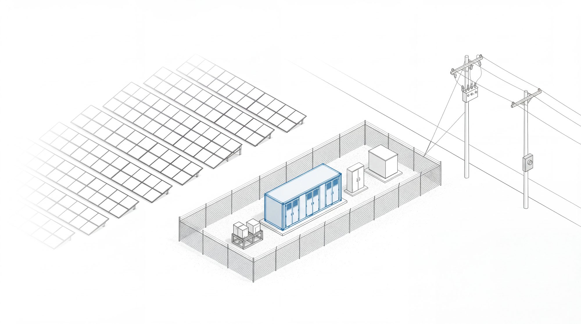 Solar invertersBattery invertersStep-up transformerUtility meterUtility recloserInverter stop signal
Equipment key
- 1Solar inverters.
Turn solar power into grid power. They accept an output limit from the controller.
Owner: the site.
- 2Battery inverters.
Charge and discharge the battery. They accept an output limit from the controller.
Owner: the site.
- 3Step-up transformers.
Raise the voltage to the 13.2 kV site bus.
Owner: the site.
- 4Site main breaker.
The switch the relay opens.
Owner: the site.
- 5Power plant controller.
The daily limiter. It measures export at the PCC and tells both inverter groups what to do.
Owner: the site.
- 6Protection relay with directional power control.
The backstop. Utility grade, with its own current and voltage sensors. It trips the breaker if export goes over the setting. It can open the site main breaker, the utility recloser, or both.
Owner: the site, or the electric utility inside its recloser.
- 7Utility meter.
Measures what crosses to the grid.
Owner: the electric utility.
- 8Utility recloser with remote control.
The electric utility can open it from its control room.
Owner: the electric utility.
- 9Lockout relay (device 86).
The trip signal rarely goes straight to the breaker alone. It energizes this relay. The lockout relay trips the breaker or the recloser and holds it open until a technician resets it by hand. The plant cannot reconnect to a dead grid by accident.
Owner: the site, or the electric utility.
- 10Inverter stop signal (runback or gate block).
Some utility schemes also send the trip to the power plant controller or straight to the inverters. The inverters stop current within milliseconds. That reduces wear on the breaker or recloser contacts as they open.
Owner: the site.
Excerpts from one electric utility
| Rule | Exact words | Source |
|---|---|---|
| The study uses the declared limit | “operating characteristics including maximum export and import capacity shall be utilized, except that fault current contribution shall be evaluated based on aggregate AC nameplate rating” | The state rule this utility follows [E1] |
| A limited site needs a relay | “For energy storage systems or distributed generation where net export is limited, Reverse Power (Function 32) shall be required.” | The state rule this utility follows [E1] |
| The utility wants utility grade controls | “The customer shall utilize a power limiting scheme (e.g. 32 element) with utility grade controls. PT, CT, and relay percent error will be factored into the final setpoint of the 32 element.” (32 element: a protection relay with directional power control.) | The utility's own bulletin, Section 7.6.14 [E2] |
| A lockout relay has a standard device number | “86 Lock Out Relay” (From the bulletin's table of device numbers.) | The utility's own bulletin [E2] |
| What a stop signal makes the inverters do | “Cease to Energize: Cessation of energy flow capability.” | The state rule this utility follows [E1] |
Three things to plan for
- The setting sits below the limit. Sensor and relay error come off the top. One electric utility says a relay in its recloser at a 5,000 kVA site “may require a reduction in site export by as much as 7.5%”.[E2 Section 7.6.14.2]
- Fault current is studied at full nameplate. A 5 MW array plus a 5 MW battery counts as 10 MW for protection.[E1]
- The export limit and the charging limit go on the storage application form, Appendix K. The utility studies what that form says.[E1]
Another way to build it
It depends on where the solar inverters are.
The rules name both layouts: DC coupled and AC coupled.[E1 Appendix K, page 2][E2 Section 5.1.1.4, page 11]
One main inverter: the battery sits behind it
One main solar inverterBattery joins on the DC sideDC link- Nameplate is 5 MW, not 10 MW. The one inverter sets it.[E1 Appendix K, page 2]
- Fault current is studied at 5 MW.[E1]
- If the study limit is below 5 MW, the controller and the relay from Figure 2 are still needed.[E1]
- Trade-off: the array and the battery share one 5 MW path. The battery charges from the grid only if the inverter works in both directions.
Many small inverters across the array: use Figure 2
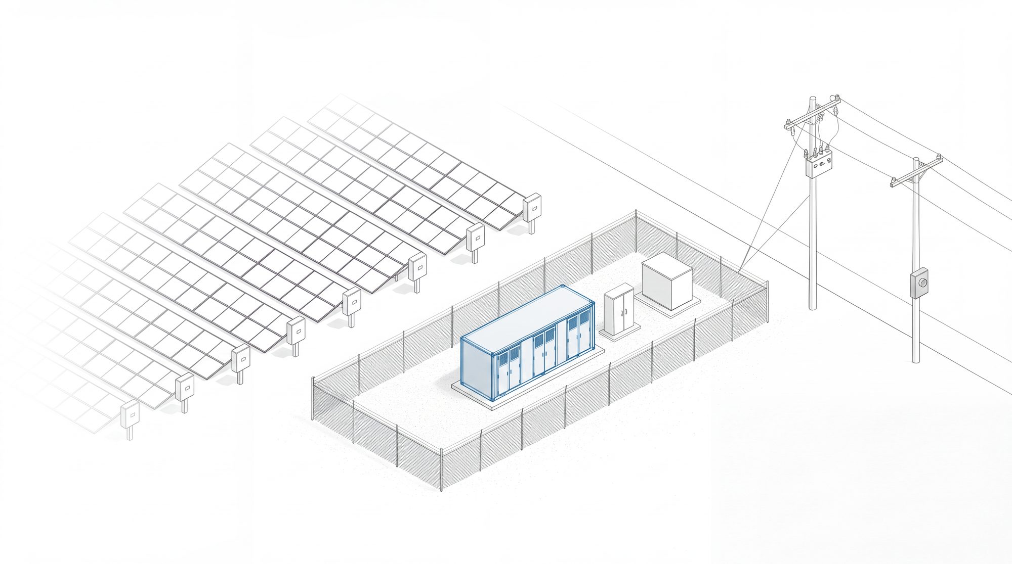 A small inverter at each rowBattery with its own invertersController and relay
- There is no single point for the battery to sit behind. Each small inverter makes grid power at its own row.
- The battery needs its own inverters. Nameplate adds up to 10 MW.[E1]
- Use the Figure 2 equipment: the controller, the protection relay with directional power control, and the main breaker.[E1][E2 Section 7.6.14]
- The controller must be able to turn down every small inverter. Confirm this with the inverter maker.
Excerpts on the two layouts
| Exact words | Source |
|---|---|
| “Indicate DER system nameplate rating based on the proposed project configuration, i.e., stand-alone, AC-coupled or DC-coupled.” | The state rule, Appendix K, item d [E1] |
| “(2) Distributed Generator (DG) and ESS DC coupled; (3) DG and ESS AC coupled” | The utility's own bulletin, Section 5.1.1.4 [E2] |
Details
Abbreviations
- CT, PT
- current transformer and potential (voltage) transformer. Sensors that feed the relay.
- Device 32
- the standard number for a directional power relay.
- Device 86
- the standard number for a lockout relay.
- Gate block
- a command that makes an inverter stop current at once.
- PCC
- point of common coupling. Where the site meets the utility line.
- kVA, MW
- units of power. 5,000 kVA is about 5 MW.
- DC coupled
- the battery and the solar share one inverter.
- AC coupled
- each has its own inverters.
- Direct transfer trip (DTT)
- the utility opens the site's breaker from a distance, over a communication channel. The state rule defines it as “Remote operation of a circuit breaker by means of a communication channel.”[E1]
Sources
Each source is a public document.
- E1. New York State Standardized Interconnection Requirements, effective October 1, 2026, section on Hybrid Projects and energy storage (Step 2, Protection and Control Review), the protective function table and Appendix K, item d, and the Glossary of Terms (Section III). Printed pages 18, 25, 32 and 33 (PDF pages 21, 28, 35 and 36); Appendix K page 2 (PDF page 108). https://dps.ny.gov/system/files/documents/2026/10/24-e-0621-et-al.-sirs-effective-october-1-2026.pdf. Read November 14, 2026.
- E2. One electric utility's interconnection bulletin, 2024 edition, Section 5.1.1.4 (printed page 11) and Sections 7.6.14, 7.6.14.1 and 7.6.14.2 (printed pages 41 and 42), and Exhibit 1, List of Standard Device Numbers (printed page 38). Read November 14, 2026.